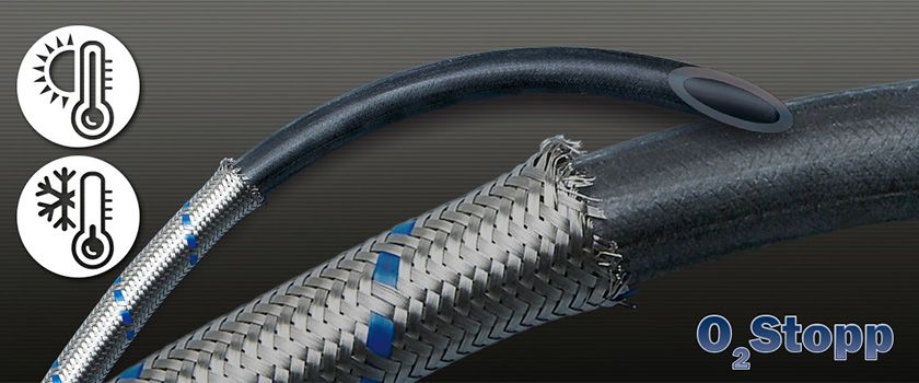
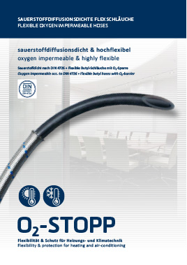
O2 STOPP
OXYGEN IMPERMEABLE & HIGHLY FLEXIBLE
The hose material O2-Stopp stands out for its excellent mechanical resilience and its high thermal resistance. It is most flexible and easy to install. The material has been examined for its oxygen diffusion behaviour acc. to DIN 4726. In order to be classified as oxygen impermeable acc. to DIN a maximum of 0,36 mg of oxygen per m² and per day is limit to diffuse into the inside of the hose. O2-Stopp undercuts this limit with an amount of only 0,32 mg of oxygen per m² and per day (≙ 0,13 g/m³d at a pipe diameter DN 12 and a testing temperature of 80 °C). The exclusion of oxygen stops corrosion as well as the growth of bacteria and consequently prevents the silting in heating and air-conditioning systems.
CERTIFICATIONS
Applicable certifications pertaining to various dimensions will be gathered from the tables listed below.
flexibility & protection for heating and air-conditioning
Due to its oxygen impermeability O2Stopp is ideally suited for the connection of:
| within a temperature range of up to: |
|
|
|
|
|
|
+ 90 ° C |
| maximum operating pressure: |
|
|
|
|
|
|
|
| DN |
8 |
10 |
12 |
|
|
|
15 bar |
| DN |
15 |
|
|
|
|
|
12 bar |
| DN |
20 |
25 |
32 |
|
|
|
10 bar |
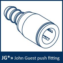
Caution >> For plug connections different operating pressures and temperatures apply!
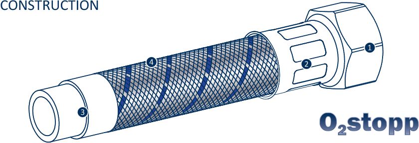
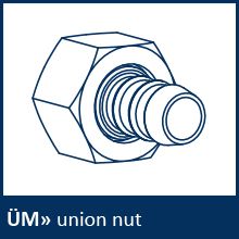
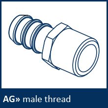
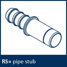
- standard connection fittings nickel-plated brass / blank or custom-made
- ferrule made of stainless steel AISI resp. made of aluminium as of DN 15
- flexible and mechanically resilient ethylene-propylene-dien-caotchouc (Butyl)
- high-quality braiding made of stainless steel AISI upon request also other braiding materials possible
The hose material O2-Stop stands out for its excellent mechanical resilience and its high thermal resistance. It is most flexible and easy to install. The material has been examined for its oxygen diffusion behaviour acc. to DIN 4726. In order to be classified as oxygen impermeable acc. to DIN a maximum of 3,6 mg of oxygen per m² and per day is limit to diffuse into the inside of the hose. O2-Stopp undercuts this limit with an amount of only 0,32 mg of oxygen per m² and per day (≙ 0,13 g/m³d at a pipe diameter DN 12 and a testing temperature of 80 °C).
The exclusion of oxygen stops corrosion as well as the growth of bacteria and consequently prevents the silting in heating and air-conditioning systems.
| |
DN |
8 |
10 |
13 |
15 |
20 |
25 |
32 |
40 |
50 |
| inner diameter in mm |
|
8,5 |
10 |
13 |
16 |
20 |
25,5 |
32 |
41 |
51 |
| outside diameter in mm* |
|
12,5 |
15 |
18,5 |
23 |
28 |
34,5 |
43 |
54 |
64 |
| wall thickness in mm |
|
1,6 |
2 |
2,3 |
3 |
3,5 |
4 |
5 |
6 |
6 |
| max. operating pressure in bar |
|
15 |
15 |
15 |
12 |
10 |
10 |
10 |
6 |
6 |
| max. operating temperature |
|
+ 90 ° C |
| * with braiding |
|
|
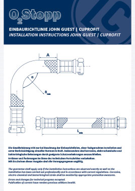
| DN |
A/R min |
L min |
L min
α = 90 ° |
L min
α = 180 ° |
L min
α = 360 ° |
| 8 |
35 |
60 |
170 |
235 |
365 |
| 10 |
40 |
60 |
205 |
280 |
430 |
| 13 |
60 |
80 |
285 |
395 |
610 |
| 15 |
70 |
95 |
325 |
450 |
710 |
| 20 |
80 |
100 |
370 |
515 |
810 |
| 25 |
100 |
125 |
460 |
640 |
1010 |
| 32 |
160 |
140 |
705 |
990 |
1560 |
| 40 |
180 |
160 |
790 |
1115 |
1770 |
| 50 |
230 |
210 |
985 |
1400 |
2225 |
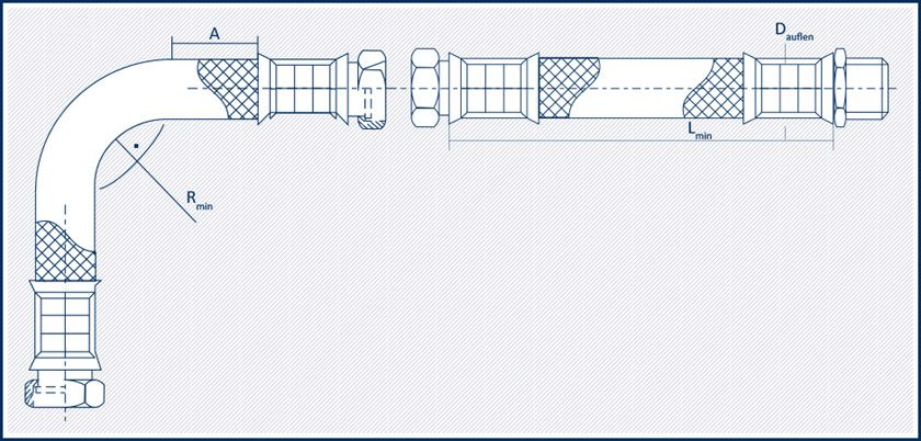
measurements in mm. All quotations (excluding diameter) are minimum measurements and shall be exceeded when possible.
The guarantee shall apply only if the directions mentioned above are observed exactly as well as the installation has been carried out professionally and in accordance with current regulations. Corrosive, electro-chemical and bacteriological strain shall be avoided by appropriate protection measures. Errors and changes for technical progress excepted. Publication of current issue renders previous editions invalid.
For inquiries, please contact us directly!
PRODUKTIONSSTANDORT
Head of
Customer Services
ANDRÉ SCHOLZ
Telefon +49 371 2399 - 0
Telefax +49 371 2399230
eMail vertrieb@lindner-armaturen.de
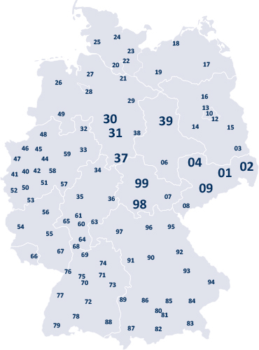
Dieses Postleitzahlengebiet ist derzeitig nicht von unserem Außendienst besetzt. Unsere Ansprechpartner am Produktionsstandort beraten Sie gern.

Field Staff / Sales Engineer
JENS HACKE
Telefon +49 371 2399-205
Telefax +49 371 2399-230
Mobil +49 162 2022755
eMail jens.hacke@lindner-armaturen.de
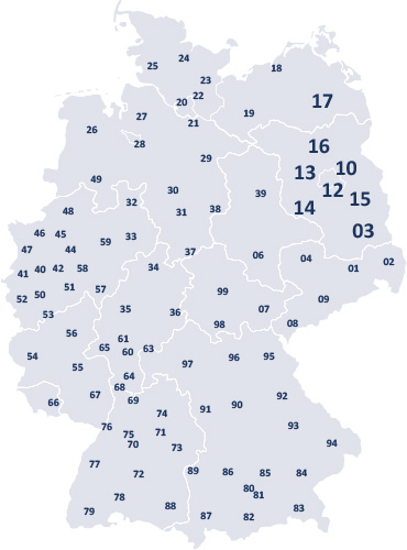
PLZ GEBIETE
01 - 02
04 - 09
30 - 31
37 - 39
98 - 99

Trade Representative
MAXIMILIAN LINDNER
Mobil +49 160 4407080
eMail maximilian.lindner
@lindner-armaturen.de
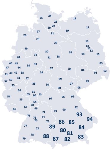
PLZ GEBIETE
80 - 89
93 - 94

Trade Representative
GERD KLIMKE
Dipl.-Ing. (FH)
Telefon +49 371 2399-252
Telefax +49 371 2399-253
Mobil +49 160 4790577
eMail gerd.klimke@lindner-armaturen.de
Head of
Customer Services
ANDRÉ SCHOLZ
Telefon +49 371 2399 - 0
Telefax +49 371 2399230
eMail vertrieb@lindner-armaturen.de

Export / Sales
JAN BERGER
Telefon 0049 371 2399-0
Telefax 0049 371 8448208
eMail export@lindner-armaturen.de

Export / Sales
SUSANN NIEHER
Telefon +49 371 2399-0
Telefax +49 371 8448208
eMail export@lindner-armaturen.de

Export / Sales
ROBERT ARZIG
Telefon +49 371 2399-0
Telefax +49 371 8448208
eMail export@lindner-armaturen.de
DISCLAIMERThe information on this product page, in particular illustrations, descriptions, dimensions and weights, is not binding. This is because technical progress means that our products are continually being developed and perfected. The general terms and conditions of business of Lindner Armaturen GmbH apply.